Python CHIP-8 Implementation
Motivation
For a while I was looking for a fun small project to learn Python. I had never used Python before and it would definitely be a good addition to my skillset. When Pablo came up with the idea to create a CHIP-8 interpreter in Python, I figured, why not. The source code can be found on my github.
What is the CHIP-8?
CHIP-8 is an interpreted programming language, developed by Joseph Weisbecker. It was initially used on the COSMAC VIP and Telmac 1800 8-bit microcomputers in the mid-1970s. CHIP-8 programs are run on a CHIP-8 virtual machine with the goal to make it easier for video games to be programmed for said computers. Currently there are implementations for about every platform imaginable. The CHIP-8 also has a descendant called SCHIP (Super Chip), but sadly there aren’t that many games available.
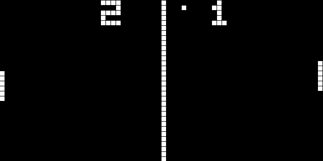 Fig 1. Screenshot of pong2
Memory
The CHIP-8 is capable of using 4KB of memory (0x000 - 0xFFF). The first 512 bytes are where the interpreter originally is located and should therefore not be used by anything else. Most programs will start at 0x200 (512), but some begin at 0x600 (1536).
Registers
The CHIP-8 has 16 8-bit data registers: V0 to VF where VF doubles as a carry flag.
Input
The input has 16 keys from 0 to F. There are three opcodes used to detect input:
- Ex9E: skip an instruction when a specific key is pressed;
- ExA1: skip an instruction if a specific key is not pressed;
- Fx0A: wait for a keypress which, when pressed, is stored in a data register.
Display
The display resolution is 64x32 and in black and white. The graphics are drawn by using sprites that are part of the CHIP-8 (digits 0 to F) or are included in the loaded program. Each CHIP-8 digit is 5 bytes long and is stored in the first part of the memory between 0x000 to 0x1FF. An example of 0 is:
11110000
10010000
10010000
10010000
11110000
Timers & Sound
The CHIP-8 has two timers that count down at 60 hertz until they reach zero.
- Delay timer: this timer is used to time game events;
- Sound timer: while the timer is greater than zero the CHIP-8 beeps.
OpCodes
The CHIP-8 has 35 different OpCodes for math, graphics and flow control. All instructions are two bytes long and are stored big-endian. The following table lists all opcodes in hexadecimal in combination with a couple of symbols:
- nnn: A 12-bit value, the lowest 12 bits of the instruction
- kk: An 8-bit value, the lowest 8 bits of the instruction
- n: A 4-bit value, the lowest 4 bits of the instruction
- x: A 4-bit value, the lower 4 bits of the high byte of the instruction
- y: A 4-bit value, the upper 4 bits of the low byte of the instruction
| OpCode | Description |
|---|---|
| 0nnn | Jump to a machine code routine at nnn. This instruction is only used on the old computers on which Chip-8 was originally implemented. It is ignored by modern interpreters. |
| 00E0 | Clear the display. |
| 00EE | Return from a subroutine. The interpreter sets the program counter to the address at the top of the stack, then subtracts 1 from the stack pointer. |
| 1nnn | Jump to location nnn. The interpreter sets the program counter to nnn. |
| 2nnn | Call subroutine at nnn. The interpreter increments the stack pointer, then puts the current PC on the top of the stack. The PC is then set to nnn. |
| 3xkk | Skip next instruction if Vx = kk. The interpreter compares register Vx to kk, and if they are equal, increments the program counter by 2. |
| 4xkk | Skip next instruction if Vx != kk. The interpreter compares register Vx to kk, and if they are not equal, increments the program counter by 2. |
| 5xy0 | Skip next instruction if Vx = Vy. The interpreter compares register Vx to register Vy, and if they are equal, increments the program counter by 2. |
| 6xkk | Set Vx = kk. The interpreter puts the value kk into register Vx. |
| 7xkk | Set Vx = Vx + kk. Adds the value kk to the value of register Vx, then stores the result in Vx. |
| 8xy0 | Set Vx = Vy. Stores the value of register Vy in register Vx. |
| 8xy1 | Set Vx = Vx OR Vy. Performs a bitwise OR on the values of Vx and Vy, then stores the result in Vx. A bitwise OR compares the corrseponding bits from two values, and if either bit is 1, then the same bit in the result is also 1. Otherwise, it is 0. |
| 8xy2 | Set Vx = Vx AND Vy. Performs a bitwise AND on the values of Vx and Vy, then stores the result in Vx. A bitwise AND compares the corrseponding bits from two values, and if both bits are 1, then the same bit in the result is also 1. Otherwise, it is 0. |
| 8xy3 | Set Vx = Vx XOR Vy. Performs a bitwise exclusive OR on the values of Vx and Vy, then stores the result in Vx. An exclusive OR compares the corrseponding bits from two values, and if the bits are not both the same, then the corresponding bit in the result is set to 1. Otherwise, it is 0. |
| 8xy4 | Set Vx = Vx + Vy, set VF = carry. The values of Vx and Vy are added together. If the result is greater than 8 bits (i.e., > 255,) VF is set to 1, otherwise 0. Only the lowest 8 bits of the result are kept, and stored in Vx. |
| 8xy5 | Set Vx = Vx - Vy, set VF = NOT borrow. If Vx > Vy, then VF is set to 1, otherwise 0. Then Vy is subtracted from Vx, and the results stored in Vx. |
| 8xy6 | Set Vx = Vx SHR 1. If the least-significant bit of Vx is 1, then VF is set to 1, otherwise 0. Then Vx is divided by 2. |
| 8xy7 | Set Vx = Vy - Vx, set VF = NOT borrow. If Vy > Vx, then VF is set to 1, otherwise 0. Then Vx is subtracted from Vy, and the results stored in Vx. |
| 8xyE | Set Vx = Vx SHL 1. If the most-significant bit of Vx is 1, then VF is set to 1, otherwise to 0. Then Vx is multiplied by 2. |
| 9xy0 | Skip next instruction if Vx != Vy. The values of Vx and Vy are compared, and if they are not equal, the program counter is increased by 2. |
| Annn | Set I = nnn. The value of register I is set to nnn. |
| Bnnn | Jump to location nnn + V0. The program counter is set to nnn plus the value of V0. |
| Cxkk | Set Vx = random byte AND kk. The interpreter generates a random number from 0 to 255, which is then ANDed with the value kk. The results are stored in Vx. See instruction 8xy2 for more information on AND. |
| Dxyn | Display n-byte sprite starting at memory location I at (Vx, Vy), set VF = collision. The interpreter reads n bytes from memory, starting at the address stored in I. These bytes are then displayed as sprites on screen at coordinates (Vx, Vy). Sprites are XORed onto the existing screen. If this causes any pixels to be erased, VF is set to 1, otherwise it is set to 0. If the sprite is positioned so part of it is outside the coordinates of the display, it wraps around to the opposite side of the screen. See instruction 8xy3 for more information on XOR, and section 2.4, Display, for more information on the Chip-8 screen and sprites. |
| Ex9E | Skip next instruction if key with the value of Vx is pressed. Checks the keyboard, and if the key corresponding to the value of Vx is currently in the down position, PC is increased by 2. |
| ExA1 | Skip next instruction if key with the value of Vx is not pressed. Checks the keyboard, and if the key corresponding to the value of Vx is currently in the up position, PC is increased by 2. |
| Fx07 | Set Vx = delay timer value. The value of DT is placed into Vx. |
| Fx0A | Wait for a key press, store the value of the key in Vx. All execution stops until a key is pressed, then the value of that key is stored in Vx. |
| Fx15 | Set delay timer = Vx. DT is set equal to the value of Vx. |
| Fx18 | Set sound timer = Vx. ST is set equal to the value of Vx. |
| Fx1E | Set I = I + Vx. The values of I and Vx are added, and the results are stored in I. |
| Fx29 | Set I = location of sprite for digit Vx. The value of I is set to the location for the hexadecimal sprite corresponding to the value of Vx. See section 2.4, Display, for more information on the Chip-8 hexadecimal font. |
| Fx33 | Store BCD representation of Vx in memory locations I, I+1, and I+2. The interpreter takes the decimal value of Vx, and places the hundreds digit in memory at location in I, the tens digit at location I+1, and the ones digit at location I+2. |
| Fx55 | Store registers V0 through Vx in memory starting at location I. The interpreter copies the values of registers V0 through Vx into memory, starting at the address in I. |
| Fx65 | Read registers V0 through Vx from memory starting at location I. The interpreter reads values from memory starting at location I into registers V0 through Vx. |
Design & Implementation
The decision was made to divide the different parts of the CHIP-8 in classes: Chip8, CPU, InputHandler and Screen.
Chip8
The Chip8 class creates the instances of all the different parts and contains the main loop.
CPU
The CPU has all the functions for the opcodes, the two timers, the CHIP-8 digits and it loads the rom.
InputHandler
The InputHandler uses Pyglet to handle all the keyboard input. At the moment there is only one preset for the keys, but it would be nice to include multiple configurations for the different games.
Screen
The Screen also uses Pyglet to handle the actual drawing, but this is only done after a specific opcode (Dxyn) as it would be a waste of resources to draw every cycle.
Bugs
There currently aren’t any known bugs, but if you do find one, please let me know.
What’s next?
One of the options is to create a NES emulator in C, but we’ll have to see if there is enough time for that in the near future.